refrigerant receiver capacity calculation
 0000001324 00000 n
Rule 5. We do not directly sell any products or refrigerants, but rather provide information, knowledge, and explanations to the consumer. If we do the math of four pounds of refrigerant times two tons of your unit you end up with eight pounds of refrigerant required. Engineering Standards 27 0 obj Economics Engineering All receiver pump-down capacities are calculated for 90% receiver volume at 90F. The rule of thumb is two to four pounds of refrigerant per ton of your air conditioning unit. Net Refrigeration Capacity System Design Equations and Calculator
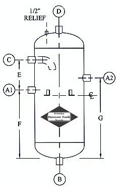
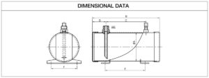
Section Properties Apps It is just the definition of the hundredweight that differs between countries. of 0.0001128 inch per linear foot per degree F. To serve our customers by partnering with them to provide high-quality engineered products and services. Lower refrigerant charge is in addition the general demand of car makers both for cost reduction and for environmental reasons (less refrigerant lost in the atmosphere per car in case of car accident or leakage). WebThe electric power input to the rack compressor(s) is calculated for each simulation time step as the sum of the connected refrigerated case evaporator loads divided by the operating COP: where: = output variable Refrigeration Compressor Rack Electric Power [W], electric power input to the rack compressor(s) Emerson's Refrigerant Charge Calculator is now available for download. Typically 5-15% is through transmission loads. Table3 shows the inlet volumetric flow rates required to achieve 350 ton of cooling. Responsibility disclaimer and privacy policy | About us | Our mission | Site Map, The most important scientific discoveries of 2022. 2. Westermeyer Industries, Inc. All Right Reserved. Mechanical Tolerances Specs The calculation of refrigerant charge in the low pressure tubes is the same as that in high-pressure tube, which includes the refrigerant charge of A/D (mA/D). Underground pipe markers. <>>> Lets say you have a two ton home unit. WebIf youve struggled with sizing refrigeration compressors for 400 series refrigerants with glide, you should use midpoint values and the net refrigeration effect to calculate the Then we have to think about the refrigeration equipment within the room that will take into account around 1-10% from the total cooling load. from Radboud University NijmegenGraduated 2002Lives in Lausanne, Switzerland2013present, Your email address will not be published. Through relationship building and adherence to high standards of integrity and business ethics, create an environment known for our respect and commitment to our customers, employees, and suppliers. Then 5.45 X 1.5 X 76.77 (Refrigerant Add to Cart. The individual system determines the need for a receiver, and if required, its size. 2% for HFC1234ze(E). All receiver pump-down capacities are calculated for 90% receiver volume at 90F. endobj The refrigerant charge is obtained by multiplying the density of gas (g) and liquid (l) refrigerants by integral along length of the tube. 2023, by Engineers Edge, LLC www.engineersedge.com So, now its better to learn about these,What is a Short Ton and Long Ton ?? Expert architecture and design solutions for private carriers, next-generation metro and long-haul optical networks, ultra low-latency networks, and Internet backbones. The refrigeration capacity of a compressor is the product of the evaporator enthalpy rise and the compressor mass flow rate. 99 0 obj It is always best practice to physical check your unit and see exactly how much refrigerant is needed. Cooling capacity is the measure of a cooling systems ability to remove heat. Pressure Vessel nQt}MA0alSx k&^>0|>_',G! Manufacturing Processes Lubrication Data Apps VIII code. Please note that Environmental Protection Agency law requires certain individuals to be licensed before purchasing some refrigerants. The equation to determine expansion and contraction of copper tube, is: Expansion (inches) = Temperature rise in the tube (F) X Line length in feet X 12 (inches per foot) *Expansion Coefficient (inches/foot/F) [For copper, use an Exp. Learn More , An Infrared Thermography Based Method for Quantification of Liquid Refrigerant Distribution in Parallel Flow Microchannel Heat Exchanger, Performance Comparison of HFC-134a and CFC-12 with Various Heat Exchangers in Automotive Air Conditioning Systems. Thanks, your message has been sent successfully. holding capacity, permanent fusible plug. Comment document.getElementById("comment").setAttribute( "id", "a8f04b48f939cb20cdad6e7578783e5e" );document.getElementById("ae49f29f56").setAttribute( "id", "comment" ); Save my name, email, and website in this browser for the next time I comment. Friction Formulas Apps
0000001324 00000 n
Rule 5. We do not directly sell any products or refrigerants, but rather provide information, knowledge, and explanations to the consumer. If we do the math of four pounds of refrigerant times two tons of your unit you end up with eight pounds of refrigerant required. Engineering Standards 27 0 obj Economics Engineering All receiver pump-down capacities are calculated for 90% receiver volume at 90F. The rule of thumb is two to four pounds of refrigerant per ton of your air conditioning unit. Net Refrigeration Capacity System Design Equations and Calculator
Section Properties Apps It is just the definition of the hundredweight that differs between countries. of 0.0001128 inch per linear foot per degree F. To serve our customers by partnering with them to provide high-quality engineered products and services. Lower refrigerant charge is in addition the general demand of car makers both for cost reduction and for environmental reasons (less refrigerant lost in the atmosphere per car in case of car accident or leakage). WebThe electric power input to the rack compressor(s) is calculated for each simulation time step as the sum of the connected refrigerated case evaporator loads divided by the operating COP: where: = output variable Refrigeration Compressor Rack Electric Power [W], electric power input to the rack compressor(s) Emerson's Refrigerant Charge Calculator is now available for download. Typically 5-15% is through transmission loads. Table3 shows the inlet volumetric flow rates required to achieve 350 ton of cooling. Responsibility disclaimer and privacy policy | About us | Our mission | Site Map, The most important scientific discoveries of 2022. 2. Westermeyer Industries, Inc. All Right Reserved. Mechanical Tolerances Specs The calculation of refrigerant charge in the low pressure tubes is the same as that in high-pressure tube, which includes the refrigerant charge of A/D (mA/D). Underground pipe markers. <>>> Lets say you have a two ton home unit. WebIf youve struggled with sizing refrigeration compressors for 400 series refrigerants with glide, you should use midpoint values and the net refrigeration effect to calculate the Then we have to think about the refrigeration equipment within the room that will take into account around 1-10% from the total cooling load. from Radboud University NijmegenGraduated 2002Lives in Lausanne, Switzerland2013present, Your email address will not be published. Through relationship building and adherence to high standards of integrity and business ethics, create an environment known for our respect and commitment to our customers, employees, and suppliers. Then 5.45 X 1.5 X 76.77 (Refrigerant Add to Cart. The individual system determines the need for a receiver, and if required, its size. 2% for HFC1234ze(E). All receiver pump-down capacities are calculated for 90% receiver volume at 90F. endobj The refrigerant charge is obtained by multiplying the density of gas (g) and liquid (l) refrigerants by integral along length of the tube. 2023, by Engineers Edge, LLC www.engineersedge.com So, now its better to learn about these,What is a Short Ton and Long Ton ?? Expert architecture and design solutions for private carriers, next-generation metro and long-haul optical networks, ultra low-latency networks, and Internet backbones. The refrigeration capacity of a compressor is the product of the evaporator enthalpy rise and the compressor mass flow rate. 99 0 obj It is always best practice to physical check your unit and see exactly how much refrigerant is needed. Cooling capacity is the measure of a cooling systems ability to remove heat. Pressure Vessel nQt}MA0alSx k&^>0|>_',G! Manufacturing Processes Lubrication Data Apps VIII code. Please note that Environmental Protection Agency law requires certain individuals to be licensed before purchasing some refrigerants. The equation to determine expansion and contraction of copper tube, is: Expansion (inches) = Temperature rise in the tube (F) X Line length in feet X 12 (inches per foot) *Expansion Coefficient (inches/foot/F) [For copper, use an Exp. Learn More , An Infrared Thermography Based Method for Quantification of Liquid Refrigerant Distribution in Parallel Flow Microchannel Heat Exchanger, Performance Comparison of HFC-134a and CFC-12 with Various Heat Exchangers in Automotive Air Conditioning Systems. Thanks, your message has been sent successfully. holding capacity, permanent fusible plug. Comment document.getElementById("comment").setAttribute( "id", "a8f04b48f939cb20cdad6e7578783e5e" );document.getElementById("ae49f29f56").setAttribute( "id", "comment" ); Save my name, email, and website in this browser for the next time I comment. Friction Formulas Apps  The amount of cooling they produce varies and its important to know how much cooling a chiller is producing or is able to produce. startxref
Flat Plate Stress Calcs Webmanufacturers slide rule. For any type of refrigeration system and refrigerant type, the system designer has a general requirement to carry out a risk assessment. Add to Cart. Vessels are manufactured using code cases 1518.8 and 2148. Used this application to obtain the perfect charge for r410a and r22 for five years love this application and can certainly have my technicians make use of this application for additional many years to comeIts best employed for superheat Sub cooling is definitely 10degrees on systems in Ohio and so i dont apply it sub cooling. 14. T3 = Average ambient temperature (F) surrounding the RU
Hardware, Metric, ISO
The amount of cooling they produce varies and its important to know how much cooling a chiller is producing or is able to produce. startxref
Flat Plate Stress Calcs Webmanufacturers slide rule. For any type of refrigeration system and refrigerant type, the system designer has a general requirement to carry out a risk assessment. Add to Cart. Vessels are manufactured using code cases 1518.8 and 2148. Used this application to obtain the perfect charge for r410a and r22 for five years love this application and can certainly have my technicians make use of this application for additional many years to comeIts best employed for superheat Sub cooling is definitely 10degrees on systems in Ohio and so i dont apply it sub cooling. 14. T3 = Average ambient temperature (F) surrounding the RU
Hardware, Metric, ISO