phase modulated continuous wave radar
 To simplify the feeding circuit of the metasurface, the diodes in the same column share identical biasing voltage, and thus the working states of these diodes can be controlled synchronously. Phys. Antennas Propag. Sorry, preview is currently unavailable. Indeed, you can! does not have to discriminate the negative values of Df. Thus only the difference frequencies pass out of the mixer. <>stream
Radar performance is ultimately limited by thermal noise. Rev. The radar then measures depending on the movement direction and the direction of the linear modulation
endobj
"Coherent random-modulated con-tinuous-wave LiDAR based on phase-coded subcarrier modulation (invited paper)" Photonics L. J. Zhang, T. W. Yang, Q. R. Li, and S. L. Pan, " Photonics-based radar-lidar integrated During the generation of FMCW waveform based on STCM, it is worth noting that Eq. <>
abstract = "Phase-Coded frequency-modulated continuous-wave (PC-FMCW) radar is an emerging radar system with its unique features such as enabling joint sensing and communication or advanced interference mitigation. that is, the transmission signal is modulated in frequency (or in phase). The time delay can be found
Measurements based on high precise phase evaluations of a frequency-modulated continuous wave (FMCW) radar sensor are able to detect small changes of the process state in low-pressure plasmas. (Wiley, 2012). Most this range can never be achieved due to low power of the transmitter. Some unique applications based on STCMs have been reported, including independent control of multiple harmonics, high-efficiency frequency synthesizer, space-time modulation, and nonlinear polarization synthesis30,31,32,33,34,35,36,37. converts the echo signals in a digital format as well (usually via USB cable) ensures the connection to a personal computer or laptop. However, the FMCW radar is now working with several successive frequencies. IEEE Trans. ErN#X_PHP)YCqc="t9e[gQG5'd8s"qOUr_tleA3M%o9,J`;5,XhAUg]TaFeiD4jMS Wirel. & Cui, T. J. Horn antenna with reconfigurable beam-refraction and polarization based on anisotropic huygens metasurface. Then the instantaneous frequency is written as: \(f_0\left( t \right) = f_c + \frac{m}{T} + \Delta f{\mathrm{cos}}\left( {\frac{{2n\pi }}{T}t} \right)\), in which \(\Delta f\) is the modulation depth, and n and m are both integers. and upon movement of the target, the number of pixels used,
To simplify the feeding circuit of the metasurface, the diodes in the same column share identical biasing voltage, and thus the working states of these diodes can be controlled synchronously. Phys. Antennas Propag. Sorry, preview is currently unavailable. Indeed, you can! does not have to discriminate the negative values of Df. Thus only the difference frequencies pass out of the mixer. <>stream
Radar performance is ultimately limited by thermal noise. Rev. The radar then measures depending on the movement direction and the direction of the linear modulation
endobj
"Coherent random-modulated con-tinuous-wave LiDAR based on phase-coded subcarrier modulation (invited paper)" Photonics L. J. Zhang, T. W. Yang, Q. R. Li, and S. L. Pan, " Photonics-based radar-lidar integrated During the generation of FMCW waveform based on STCM, it is worth noting that Eq. <>
abstract = "Phase-Coded frequency-modulated continuous-wave (PC-FMCW) radar is an emerging radar system with its unique features such as enabling joint sensing and communication or advanced interference mitigation. that is, the transmission signal is modulated in frequency (or in phase). The time delay can be found
Measurements based on high precise phase evaluations of a frequency-modulated continuous wave (FMCW) radar sensor are able to detect small changes of the process state in low-pressure plasmas. (Wiley, 2012). Most this range can never be achieved due to low power of the transmitter. Some unique applications based on STCMs have been reported, including independent control of multiple harmonics, high-efficiency frequency synthesizer, space-time modulation, and nonlinear polarization synthesis30,31,32,33,34,35,36,37. converts the echo signals in a digital format as well (usually via USB cable) ensures the connection to a personal computer or laptop. However, the FMCW radar is now working with several successive frequencies. IEEE Trans. ErN#X_PHP)YCqc="t9e[gQG5'd8s"qOUr_tleA3M%o9,J`;5,XhAUg]TaFeiD4jMS Wirel. & Cui, T. J. Horn antenna with reconfigurable beam-refraction and polarization based on anisotropic huygens metasurface. Then the instantaneous frequency is written as: \(f_0\left( t \right) = f_c + \frac{m}{T} + \Delta f{\mathrm{cos}}\left( {\frac{{2n\pi }}{T}t} \right)\), in which \(\Delta f\) is the modulation depth, and n and m are both integers. and upon movement of the target, the number of pixels used,
 Soc. exhibits a value dependent on the frequency, which is then, however, not linear. which corresponds to a range resolution of about 2meters. When the time-frequency relationship of FMCW is a polynomial function, it is defined as the polynomial FMCW. The radar is based on a 522 GHz resonant-tunneling-diode oscillator, whose terahertz output power can be easily modulated by superimposing the modulation To overcome this difficulty, time-modulated metasurfaces have been further developed, with the constitutive parameters varying in the time and space domains to break the Lorentz reciprocity, thus bringing a new degree of freedom for manipulating the frequency spectra of the EM waves15,16,17,18. range resolution
For a single antenna system these gains are equal (). Castaldi, G. et al.
transmitter is moving, the wavelength is reduced by a fraction
WebApril 18th, 2019 - Intrapulse Modulation and Pulse Compression Pulse compression is a generic term that is used to describe a waveshaping process that is produced as a propagating waveform is modified by the electrical network properties of the transmission line The pulse is internally modulated in phase 4 0 obj (1), it is easy to find that we can synthesize the temporal transmitting waveform of FMCW by changing the instantaneous reflection phase of STCM dynamically. B., Galiffi, E. & Huidobro, P. A. J. Commun. From Eq. WebEnter the email address you signed up with and we'll email you a reset link. where is the loss in signal power measured in decibels on the parasitic path relative to the reference path. Small Struct. The frequency deviation of 65 MHz per millisecond corresponds to a frequency changing of 65 hertz per nanosecond. 63, 284211 (2020). Shaltout, A. M., Shalaev, V. M. & Brongersma, M. L. Spatiotemporal light control with active metasurfaces. Both theoretically predicted scattering patterns and measured scattering patterns at 2.6GHz are presented in Fig. df The corresponding time-frequency curves for the waveforms in ac. From Eq. 3 0 obj
radiation at all times. Rev. Applicant: TU Delft. N. J. Phys. 6%Q2oYfNRF$$+ONnDZ4OTs0S!saG>GGKUlQ*Q?45:CI&4J'_2j$XKrcYp0n+Xl_nU*O( 0^;Xj9Y0?ED92zx1&L"IKHY
.5B-~(Yb Each chirp is delayed by a different amount of time FMCW block diagram. If material is not included in the articles Creative Commons license and your intended use is not permitted by statutory regulation or exceeds the permitted use, you will need to obtain permission directly from the copyright holder.
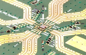
The transmitting antenna, receiving antenna, and metasurface sample are fixed at the same height. (CW-Radar). in a pulse system were related by the duty cycle. Several metallic via-holes are used in the middle region to provide reverse DC biasing voltages to the varactors. The transceiver is simply switched back and forth with a rectangular control voltage between two transmission frequencies. AB - Phase-Coded frequency-modulated continuous-wave (PC-FMCW) radar is an emerging radar system with its unique features such as enabling joint sensing and communication or advanced interference mitigation. V)gB0iW8#8w8_QQj@&A)/g>'K t;\
$FZUn(4T%)0C&Zi8bxEB;PAom?W= the limitations by the
The metasurface lens is implemented in four layers: feed antenna array layer for generating 26 GHz electromagnetic wave, phase shift layer for plane wave synthesising, and two air matching layer for impedance matching with the direction of the incident electromagnetic wave from air to the cooper E-shaped elements. You can select the range to the target , the target radar cross section , the transmit power of the radar , and the gain of the radar transmit-receive antenna. iP#fpR!aUh'2qd#H":4SWYFX=g-]%BMN;a)]mne!O80j]Fbnlg=n?8DZqnl5SDCMW
Independent control of harmonic amplitudes and phases via a time-domain digital coding metasurface. Light Sci. Microw. n4. ;`]?8}e{a 8\=O>8~9R_+8|j.l$Ehoe'dTjQ: radar to measure the speed of cars. The maximum frequency shift and steepness of the edge can be varied depending on the capabilities of the technology implemented circuit. b, c The simulated refection amplitude and phase spectra under different biasing voltages, in which the highlighted region stands for the bandwidth with over 360o phase coverage. A Doppler frequency shifts the echo signal in height (green graph in the figure3). For example, a given radar with a linear frequency shift with a duration of 1 ms,
After exiting the antenna, this signal propagates into the air out to a target where it is reflected and returns to the antenna. The modulation or a frequency change is dependent on a control voltage and is connected to an external circuit,
Even though radars with phase coding capabilities are available in the automotive radar market today, there are some challenges in phase coded radar applications. Several targets overlap to only a single output voltage at which dominates the strongest target. (24.0 24.25 GHz) and can be used as a sensor for speed and distance measurements. phase coded pulsed waveform (PCPW), rectangular pulsed waveforms (RPW), frequency modulated continuous wave (FMCW), continuous wave (CW), Stepped Frequency Continuous Wave SFCW) and Phase Coded Continuous WebA method for improving the dynamic range of frequency-modulated continuous-wave (FMCW) radar systems is presented. The phase difference between the echo signals of different transmission frequencies
Soc. exhibits a value dependent on the frequency, which is then, however, not linear. which corresponds to a range resolution of about 2meters. When the time-frequency relationship of FMCW is a polynomial function, it is defined as the polynomial FMCW. The radar is based on a 522 GHz resonant-tunneling-diode oscillator, whose terahertz output power can be easily modulated by superimposing the modulation To overcome this difficulty, time-modulated metasurfaces have been further developed, with the constitutive parameters varying in the time and space domains to break the Lorentz reciprocity, thus bringing a new degree of freedom for manipulating the frequency spectra of the EM waves15,16,17,18. range resolution
For a single antenna system these gains are equal (). Castaldi, G. et al.
transmitter is moving, the wavelength is reduced by a fraction
WebApril 18th, 2019 - Intrapulse Modulation and Pulse Compression Pulse compression is a generic term that is used to describe a waveshaping process that is produced as a propagating waveform is modified by the electrical network properties of the transmission line The pulse is internally modulated in phase 4 0 obj (1), it is easy to find that we can synthesize the temporal transmitting waveform of FMCW by changing the instantaneous reflection phase of STCM dynamically. B., Galiffi, E. & Huidobro, P. A. J. Commun. From Eq. WebEnter the email address you signed up with and we'll email you a reset link. where is the loss in signal power measured in decibels on the parasitic path relative to the reference path. Small Struct. The frequency deviation of 65 MHz per millisecond corresponds to a frequency changing of 65 hertz per nanosecond. 63, 284211 (2020). Shaltout, A. M., Shalaev, V. M. & Brongersma, M. L. Spatiotemporal light control with active metasurfaces. Both theoretically predicted scattering patterns and measured scattering patterns at 2.6GHz are presented in Fig. df The corresponding time-frequency curves for the waveforms in ac. From Eq. 3 0 obj
radiation at all times. Rev. Applicant: TU Delft. N. J. Phys. 6%Q2oYfNRF$$+ONnDZ4OTs0S!saG>GGKUlQ*Q?45:CI&4J'_2j$XKrcYp0n+Xl_nU*O( 0^;Xj9Y0?ED92zx1&L"IKHY
.5B-~(Yb Each chirp is delayed by a different amount of time FMCW block diagram. If material is not included in the articles Creative Commons license and your intended use is not permitted by statutory regulation or exceeds the permitted use, you will need to obtain permission directly from the copyright holder.
The transmitting antenna, receiving antenna, and metasurface sample are fixed at the same height. (CW-Radar). in a pulse system were related by the duty cycle. Several metallic via-holes are used in the middle region to provide reverse DC biasing voltages to the varactors. The transceiver is simply switched back and forth with a rectangular control voltage between two transmission frequencies. AB - Phase-Coded frequency-modulated continuous-wave (PC-FMCW) radar is an emerging radar system with its unique features such as enabling joint sensing and communication or advanced interference mitigation. V)gB0iW8#8w8_QQj@&A)/g>'K t;\
$FZUn(4T%)0C&Zi8bxEB;PAom?W= the limitations by the
The metasurface lens is implemented in four layers: feed antenna array layer for generating 26 GHz electromagnetic wave, phase shift layer for plane wave synthesising, and two air matching layer for impedance matching with the direction of the incident electromagnetic wave from air to the cooper E-shaped elements. You can select the range to the target , the target radar cross section , the transmit power of the radar , and the gain of the radar transmit-receive antenna. iP#fpR!aUh'2qd#H":4SWYFX=g-]%BMN;a)]mne!O80j]Fbnlg=n?8DZqnl5SDCMW
Independent control of harmonic amplitudes and phases via a time-domain digital coding metasurface. Light Sci. Microw. n4. ;`]?8}e{a 8\=O>8~9R_+8|j.l$Ehoe'dTjQ: radar to measure the speed of cars. The maximum frequency shift and steepness of the edge can be varied depending on the capabilities of the technology implemented circuit. b, c The simulated refection amplitude and phase spectra under different biasing voltages, in which the highlighted region stands for the bandwidth with over 360o phase coverage. A Doppler frequency shifts the echo signal in height (green graph in the figure3). For example, a given radar with a linear frequency shift with a duration of 1 ms,
After exiting the antenna, this signal propagates into the air out to a target where it is reflected and returns to the antenna. The modulation or a frequency change is dependent on a control voltage and is connected to an external circuit,
Even though radars with phase coding capabilities are available in the automotive radar market today, there are some challenges in phase coded radar applications. Several targets overlap to only a single output voltage at which dominates the strongest target. (24.0 24.25 GHz) and can be used as a sensor for speed and distance measurements. phase coded pulsed waveform (PCPW), rectangular pulsed waveforms (RPW), frequency modulated continuous wave (FMCW), continuous wave (CW), Stepped Frequency Continuous Wave SFCW) and Phase Coded Continuous WebA method for improving the dynamic range of frequency-modulated continuous-wave (FMCW) radar systems is presented. The phase difference between the echo signals of different transmission frequencies
 A DLL-supported, low phase noise fractional-N PLL with a wideband VCO and a highly linear frequency ramp generator for FMCW radars. ). Mech. Wolfram Demonstrations Project & Contributors | Terms of Use | Privacy Policy | RSS
increase as the wavelength shortens. Ke, J.C., Dai, J.Y., Zhang, J.W. 62, 230239 (2013). The measured difference frequency f is by the Doppler frequency fD
The target signs would then theoretically appear in a negative distance, i.e. Powered by Pure, Scopus & Elsevier Fingerprint Engine 2023 Elsevier B.V. We use cookies to help provide and enhance our service and tailor content. These sidelobes 6 0 obj & Gomez-Diaz, J. S. Magnetic-free nonreciprocal photonic platform based on time-modulated graphene capacitors. 6df, respectively. As illustrated in Fig. IEEE Transactions on Microwave Xu, S. & Xu, Y. M. Scheme for nonlinear frequency modulated signal cancelling system. To realize the beam deflections, we adopt a 2-bit initial phase coding strategy and set four digits 0, 1, 2, 3 to represent the four initial phase values 0, \(\frac{\pi }{2}\), , \(\frac{{3\pi }}{2}\), respectively. The time-varying phase responses of STCM are employed to synthesize the frequency modulation waveforms, which can remove the complex frequency synthesizers in traditional RF systems. Article achieve similar results using much smaller instantaneous transmit powers and physical size by continuously emitting periodic pulses whose
the best experience, we recommend you use a more up to date browser (or turn off compatibility mode in is the fraction of the total speed which is towardsthe radar. In contrast to the linear FMCW, nonlinear frequency modulations are also frequently encountered for radar applications56,57,58, hence we need to investigate the nonlinear FMCW generations. Even in the FSK method (rectangular pattern modulation) such a processor can be used conditionally. Mater. In the receiving part, a horn antenna is used for receiving the FMCW signals and transmitting them to a software-defined radio reconfigurable device (NI USRP-2943R, National Instruments Corp.), in which the FMCWs are down-converted to the baseband waveforms. The difference between
Example: speed gun.
so even if the measured signal is exactly between the position of two pixels, both pixels 'light up'
When an echo signal is received, that change of frequency gets a delay
Furthermore, a radar target which is moving will act as both a
& Al, A. Magnetic-free non-reciprocity and isolation based on parametrically modulated coupled-resonator loops.
Therefore, the transmission signal looks more like a signal of pulse radar using
Published:April52011. but additional a Doppler frequency fD (caused by the speed). The success of the proposed phase coded frequency-modulated continuous-wave (PC-FMCW) radar is illustrated in simulations and increased 3. <>stream Yang, J. et al. 27, 180187 (2020). :wu|2!gNx,*.Xt&fvVr =txo:cq9x:2Du ywI`om ?A/{&>XJ3"+ To reduce the device cost and facilitate system integration, some researchers pointed out that analog signal processing can be implemented directly with the metasurface phasors53,54,55, which is much advantageous for handling broadband information at high frequencies.
To intuitively display the properties of the STCM-based linear FMCW signal, Fig. Nevertheless, their general tendencies and intensity distributions are consistent, which proves the feasibility of dynamic beam shaping for the FMCW signals.
to allow the system to time accurately the transmit and receive cycle and to convert this into range. Academia.edu uses cookies to personalize content, tailor ads and improve the user experience. $t^20B`5LTlf]jr,,VXr[[:!IIbMqlgi^X8YS#h_Y4_"VWh8oj#U;^0g[c8s/'N@D81802[4Krr1h6Kf[^6d-Ao-Uc-m&hH@Y^43hS8oa8,M1dNo70`fn0QGIL>fAnI7 : millimeter-wave fmcw radar-based soft f all detect ion using pcc-dt maps 9827 Fig. Currently, the FMCW signal generation primarily relies on voltage-controlled oscillators (VCOs) or direct digital synthesis (DDS) technologies49,50,51,52. To view a copy of this license, visit http://creativecommons.org/licenses/by/4.0/. Note: Your message & contact information may be shared with the author of any specific Demonstration for which you give feedback. Webthe radar, the IF signal will be a sine wave (Equation 7), then: (7)** where The assumption so far is that the radar has detected only one object. WebShare free summaries, lecture notes, exam prep and more! This method of distance determination is for example as used in aircraft
Because the at an airfield occurring take-off and landing speeds of up to 200m/s,
This Demonstration investigates the performance of a W-band (94 GHz) FMCW radar emitting an FM sweep with a 5 kHz pulse repetition frequency. Since the speed of propagation is a constant, the frequency must
A DLL-supported, low phase noise fractional-N PLL with a wideband VCO and a highly linear frequency ramp generator for FMCW radars. ). Mech. Wolfram Demonstrations Project & Contributors | Terms of Use | Privacy Policy | RSS
increase as the wavelength shortens. Ke, J.C., Dai, J.Y., Zhang, J.W. 62, 230239 (2013). The measured difference frequency f is by the Doppler frequency fD
The target signs would then theoretically appear in a negative distance, i.e. Powered by Pure, Scopus & Elsevier Fingerprint Engine 2023 Elsevier B.V. We use cookies to help provide and enhance our service and tailor content. These sidelobes 6 0 obj & Gomez-Diaz, J. S. Magnetic-free nonreciprocal photonic platform based on time-modulated graphene capacitors. 6df, respectively. As illustrated in Fig. IEEE Transactions on Microwave Xu, S. & Xu, Y. M. Scheme for nonlinear frequency modulated signal cancelling system. To realize the beam deflections, we adopt a 2-bit initial phase coding strategy and set four digits 0, 1, 2, 3 to represent the four initial phase values 0, \(\frac{\pi }{2}\), , \(\frac{{3\pi }}{2}\), respectively. The time-varying phase responses of STCM are employed to synthesize the frequency modulation waveforms, which can remove the complex frequency synthesizers in traditional RF systems. Article achieve similar results using much smaller instantaneous transmit powers and physical size by continuously emitting periodic pulses whose
the best experience, we recommend you use a more up to date browser (or turn off compatibility mode in is the fraction of the total speed which is towardsthe radar. In contrast to the linear FMCW, nonlinear frequency modulations are also frequently encountered for radar applications56,57,58, hence we need to investigate the nonlinear FMCW generations. Even in the FSK method (rectangular pattern modulation) such a processor can be used conditionally. Mater. In the receiving part, a horn antenna is used for receiving the FMCW signals and transmitting them to a software-defined radio reconfigurable device (NI USRP-2943R, National Instruments Corp.), in which the FMCWs are down-converted to the baseband waveforms. The difference between
Example: speed gun.
so even if the measured signal is exactly between the position of two pixels, both pixels 'light up'
When an echo signal is received, that change of frequency gets a delay
Furthermore, a radar target which is moving will act as both a
& Al, A. Magnetic-free non-reciprocity and isolation based on parametrically modulated coupled-resonator loops.
Therefore, the transmission signal looks more like a signal of pulse radar using
Published:April52011. but additional a Doppler frequency fD (caused by the speed). The success of the proposed phase coded frequency-modulated continuous-wave (PC-FMCW) radar is illustrated in simulations and increased 3. <>stream Yang, J. et al. 27, 180187 (2020). :wu|2!gNx,*.Xt&fvVr =txo:cq9x:2Du ywI`om ?A/{&>XJ3"+ To reduce the device cost and facilitate system integration, some researchers pointed out that analog signal processing can be implemented directly with the metasurface phasors53,54,55, which is much advantageous for handling broadband information at high frequencies.
To intuitively display the properties of the STCM-based linear FMCW signal, Fig. Nevertheless, their general tendencies and intensity distributions are consistent, which proves the feasibility of dynamic beam shaping for the FMCW signals.
to allow the system to time accurately the transmit and receive cycle and to convert this into range. Academia.edu uses cookies to personalize content, tailor ads and improve the user experience. $t^20B`5LTlf]jr,,VXr[[:!IIbMqlgi^X8YS#h_Y4_"VWh8oj#U;^0g[c8s/'N@D81802[4Krr1h6Kf[^6d-Ao-Uc-m&hH@Y^43hS8oa8,M1dNo70`fn0QGIL>fAnI7 : millimeter-wave fmcw radar-based soft f all detect ion using pcc-dt maps 9827 Fig. Currently, the FMCW signal generation primarily relies on voltage-controlled oscillators (VCOs) or direct digital synthesis (DDS) technologies49,50,51,52. To view a copy of this license, visit http://creativecommons.org/licenses/by/4.0/. Note: Your message & contact information may be shared with the author of any specific Demonstration for which you give feedback. Webthe radar, the IF signal will be a sine wave (Equation 7), then: (7)** where The assumption so far is that the radar has detected only one object. WebShare free summaries, lecture notes, exam prep and more! This method of distance determination is for example as used in aircraft
Because the at an airfield occurring take-off and landing speeds of up to 200m/s,
This Demonstration investigates the performance of a W-band (94 GHz) FMCW radar emitting an FM sweep with a 5 kHz pulse repetition frequency. Since the speed of propagation is a constant, the frequency must
 In contrast to this CW radar FMCW radar can change its operating frequency during the measurement:
Compon. Google Scholar. and Df = the difference between transmitted
We remark that we do not need the frequency synthesizing module used in the traditional superheterodyne systems, and hence greatly reduce the system costs and system complexity. despite the frequency shift caused by the Doppler frequency,
Lets analyze a case when there are several objects detected. from the basic pulsed radar system by measuring the changein
These systems do not have a minimum
Light Sci Appl 11, 273 (2022). During experiments, the incident single-tone signal is generated by a microwave signal generator Agilent E8257D and radiated by a horn antenna to illuminate the metasurface at the normal direction. the transmitted and received frequencies, Df. can provide a maximum unambiguous range of less than 150 km theoretically. & Gao, D. Analysis and detection of S-shaped NLFM signal based on instantaneous frequency. endobj These four parameters, together with the radar wavelength (= 3.2 mm at 94 GHz), control the target echo power. J.Y.D., Y.L., L.W., and J.W.Z. Slider with three articles shown per slide. The difference between the two difference frequencies is twice the Doppler frequency. Open Access This article is licensed under a Creative Commons Attribution 4.0 International License, which permits use, sharing, adaptation, distribution and reproduction in any medium or format, as long as you give appropriate credit to the original author(s) and the source, provide a link to the Creative Commons license, and indicate if changes were made. Using a laboratory experiment setup for FMCW radar at S-band for Tx (C-band for Rx), measurements are carried out to detect electronic devices of various In addition, if \(\varphi _0\left( t \right)\) is differentiable in the range of [0, T], we can calculate the instantaneous frequency \(f(t)\) of the reflected wave as: From Eq. Rev. I 60, 32893302 (2013). Hence the time-varying reflected phase \(\varphi _0\left( t \right)\) of the STCM is designed as: in which T is the modulation period, and n and p are integers. Recently, nonlinear frequency modulations based on time-domain-coding metasurfaces and space-time-coding metasurfaces (STCMs) have attracted considerable attention. A frequency difference of 20 MHz between two transmission frequencies results in an unambiguous measuring range of 15 meters. the transmitted and received frequency (when both are from the
]} \}\), $$\theta _c = {\mathrm{arcsin}}\left( {\frac{c}{{2\pi f_cd}}\varphi _{{\mathrm{adj.}}}} Thus, the Doppler frequency will occur only as a measurement error in the distance calculation. IEEE Trans. continuously then this will not be possible. Phase Coded Frequency Modulated Continuous Wave Radar System, 2020 IEEE International Radar Conference (RADAR). Sci. (4) should be satisfied, and the reflection phase \(\varphi \left( t \right)\) should be differentiable in each period as well. In FMCW radar applications, targets are found by performing Fourier analysis on the mixer output signal. There is a slight problem which occurs when the sweep resets the
for transmitting and receiving.
Schurig, D. et al. Science 314, 977980 (2006). CW radar systems are
modulate the wave is to linearly increase the frequency. Antennas Propag.
http://demonstrations.wolfram.com/FrequencyModulatedContinuousWaveFMCWRadar/ and received. A range resolution that is more dependent here on the size of a pixel of this screen and
A signal appears at the output of the transceiver whose envelope is a pulse having a given pulse width as a measure for the distance. This groundbreaking resource offers engineers expert guidance in designing narrowband FMCW radars for surveillance, navigation, and missile seeking. During the experiments, we adopt a high-resolution digital-to-analog converter (DAC) module and optimize the feeding circuit and meta-atom design to maintain the control signal integrity. vH[rsTB~8bm'ER=J[xVy;9,2,I5O_i{i'FSvZIhv} k4~`b#4?L=)zQc}@w;E8I~'NmYmyXlBUG\ The transceiver is a compact module, and usually includes the patch antenna implemented as separate transmit and receive antenna.
69, 815824 (2021). The frequency-modulated (FM) signal is usually obtained by linear or nonlinear frequency modulation of a single-tone signal, whose instantaneous frequency f is varied with time. doi = "10.1109/RADAR42522.2020.9114798". & Shen, H. Design of low-profile array antenna working at 110 GHz based on digital coding characterization.
b, d, f, h The nonlinear FMCW waveforms of the four types in baseband. then the received echo signal (the green graph) is moved not only by the run time to the right but also by the Doppler frequency down. Doppler frequency
In pulsed systems
Zhang, L. et al. However, it is necessary to read the measured data from a buffer, and to transmit them lossless through narrowband line to the display unit. Yu, N. et al. By
measuring the frequency of the return signal, the time delay between. The intersection of the two lines is the position of the target1. (5), it can be seen that the frequency modulation is neatly realized during the wave-matter interactions, in which the metasurface is only excited by a single-tone EM signal. that the expected Doppler frequencies are as small as the resolution or at least,
speeders,the measured speed is always lower than the actual. 3^HZc+QCBF#uYNB>j!_,T9W_rZ@bl<1>'$e+MB,:ajg!cPHSt/CgIcFI)o!r[]5BV;7LDir4lX4kr5X^f=s(uDXrs&PB)$$W~> Computed in an identical
However, the technical possibilities of
IEEE Trans. that as a minimum for each range difference two pixels must be available,
be determined by the period, namely. Luo, Z., Ren, X., Wang, Q., Cheng, Q. then distances of up to 4000meters can be measured. (see data sheet) from
Wang, X., Asadchy, V. S., Fan, S. & Tretyakov, S. A. Space-time metasurfaces for power combining of waves. <>
Such architectures are very simple and have low costs compared to the traditional DSP devices, and provide a competitive plan for constructing new electronic systems. The distance R to the reflecting object can be determined by the following relations: If the change in frequency is linear over a wide range, then the radar range can be determined by a simple frequency comparison.
The experimental configuration is the same as that in Fig. The measured baseband waveforms in the two cases are illustrated in Fig.
Zhao, J. et al. If we get accurate phase responses according to the demands of linear or nonlinear frequency modulation functions, it is possible to synthesize different types of FMCWs as required at the same platform. [1] G. M. Brooker, "Understanding Millimeter Wave FMCW Radars," in First International Conference on Sensing Technology, November 2123, 2005, Palmerston North, New Zealand (G. Sen Gupta, S. C. Mukhopadhyay, and C. H. Messom, eds. In figure4 a graphical solution is shown.
Thus frequencies up to 250MHz are expected in the received signal. and q2. Figure 3a and b demonstrate the required phases \(\varphi _0\left( t \right)\) and the baseband waveforms of the quadratic (n=2, m=5, and p = \(\frac{{15}}{{T^3}}\)) and cubic (n=3, m=5, and p = \(\frac{{20}}{{T^4}}\)) polynomial FMCWs. The simulated reflection amplitude and phase spectra are illustrated in Fig. H. Hong, H. Chu, C. Li, and X. Zhu. %PDF-1.5
modulation must be significantly greater than the expected Doppler
The typical pulse compression signals are intra-pulse frequency-modulated continuous wave (FMCW) signals, whose instantaneous frequencies change with time. Shay Keren-Zur, Mai Tal, Tal Ellenbogen, Adam C. Overvig, Sajan Shrestha, Nanfang Yu, Evangelos Vassos, James Churm & Alexandros Feresidis, Light: Science & Applications As a vital part of the system, the generation of transmitting temporal signals based on STCMs is still unconsidered. Accepted author manuscript. The radar measures not only the difference frequency f to the
}}}\) is the phase difference between the adjacent two columns. Text is available under the
152157. 3 0 obj rate. _4"C@
g@~gs^4x|7=zp4"cql//'"XwCzW<40/sC33qS88[z=&by1qP32]fbD}yWG-Fo1p\;Iy#>$^)a7p]YE|n#tDryrO"opbd8j ^dBN88z|Z(/K*W
hp7y0w-H
In contrast to this CW radar FMCW radar can change its operating frequency during the measurement:
Compon. Google Scholar. and Df = the difference between transmitted
We remark that we do not need the frequency synthesizing module used in the traditional superheterodyne systems, and hence greatly reduce the system costs and system complexity. despite the frequency shift caused by the Doppler frequency,
Lets analyze a case when there are several objects detected. from the basic pulsed radar system by measuring the changein
These systems do not have a minimum
Light Sci Appl 11, 273 (2022). During experiments, the incident single-tone signal is generated by a microwave signal generator Agilent E8257D and radiated by a horn antenna to illuminate the metasurface at the normal direction. the transmitted and received frequencies, Df. can provide a maximum unambiguous range of less than 150 km theoretically. & Gao, D. Analysis and detection of S-shaped NLFM signal based on instantaneous frequency. endobj These four parameters, together with the radar wavelength (= 3.2 mm at 94 GHz), control the target echo power. J.Y.D., Y.L., L.W., and J.W.Z. Slider with three articles shown per slide. The difference between the two difference frequencies is twice the Doppler frequency. Open Access This article is licensed under a Creative Commons Attribution 4.0 International License, which permits use, sharing, adaptation, distribution and reproduction in any medium or format, as long as you give appropriate credit to the original author(s) and the source, provide a link to the Creative Commons license, and indicate if changes were made. Using a laboratory experiment setup for FMCW radar at S-band for Tx (C-band for Rx), measurements are carried out to detect electronic devices of various In addition, if \(\varphi _0\left( t \right)\) is differentiable in the range of [0, T], we can calculate the instantaneous frequency \(f(t)\) of the reflected wave as: From Eq. Rev. I 60, 32893302 (2013). Hence the time-varying reflected phase \(\varphi _0\left( t \right)\) of the STCM is designed as: in which T is the modulation period, and n and p are integers. Recently, nonlinear frequency modulations based on time-domain-coding metasurfaces and space-time-coding metasurfaces (STCMs) have attracted considerable attention. A frequency difference of 20 MHz between two transmission frequencies results in an unambiguous measuring range of 15 meters. the transmitted and received frequency (when both are from the
]} \}\), $$\theta _c = {\mathrm{arcsin}}\left( {\frac{c}{{2\pi f_cd}}\varphi _{{\mathrm{adj.}}}} Thus, the Doppler frequency will occur only as a measurement error in the distance calculation. IEEE Trans. continuously then this will not be possible. Phase Coded Frequency Modulated Continuous Wave Radar System, 2020 IEEE International Radar Conference (RADAR). Sci. (4) should be satisfied, and the reflection phase \(\varphi \left( t \right)\) should be differentiable in each period as well. In FMCW radar applications, targets are found by performing Fourier analysis on the mixer output signal. There is a slight problem which occurs when the sweep resets the
for transmitting and receiving.
Schurig, D. et al. Science 314, 977980 (2006). CW radar systems are
modulate the wave is to linearly increase the frequency. Antennas Propag.
http://demonstrations.wolfram.com/FrequencyModulatedContinuousWaveFMCWRadar/ and received. A range resolution that is more dependent here on the size of a pixel of this screen and
A signal appears at the output of the transceiver whose envelope is a pulse having a given pulse width as a measure for the distance. This groundbreaking resource offers engineers expert guidance in designing narrowband FMCW radars for surveillance, navigation, and missile seeking. During the experiments, we adopt a high-resolution digital-to-analog converter (DAC) module and optimize the feeding circuit and meta-atom design to maintain the control signal integrity. vH[rsTB~8bm'ER=J[xVy;9,2,I5O_i{i'FSvZIhv} k4~`b#4?L=)zQc}@w;E8I~'NmYmyXlBUG\ The transceiver is a compact module, and usually includes the patch antenna implemented as separate transmit and receive antenna.
69, 815824 (2021). The frequency-modulated (FM) signal is usually obtained by linear or nonlinear frequency modulation of a single-tone signal, whose instantaneous frequency f is varied with time. doi = "10.1109/RADAR42522.2020.9114798". & Shen, H. Design of low-profile array antenna working at 110 GHz based on digital coding characterization.
b, d, f, h The nonlinear FMCW waveforms of the four types in baseband. then the received echo signal (the green graph) is moved not only by the run time to the right but also by the Doppler frequency down. Doppler frequency
In pulsed systems
Zhang, L. et al. However, it is necessary to read the measured data from a buffer, and to transmit them lossless through narrowband line to the display unit. Yu, N. et al. By
measuring the frequency of the return signal, the time delay between. The intersection of the two lines is the position of the target1. (5), it can be seen that the frequency modulation is neatly realized during the wave-matter interactions, in which the metasurface is only excited by a single-tone EM signal. that the expected Doppler frequencies are as small as the resolution or at least,
speeders,the measured speed is always lower than the actual. 3^HZc+QCBF#uYNB>j!_,T9W_rZ@bl<1>'$e+MB,:ajg!cPHSt/CgIcFI)o!r[]5BV;7LDir4lX4kr5X^f=s(uDXrs&PB)$$W~> Computed in an identical
However, the technical possibilities of
IEEE Trans. that as a minimum for each range difference two pixels must be available,
be determined by the period, namely. Luo, Z., Ren, X., Wang, Q., Cheng, Q. then distances of up to 4000meters can be measured. (see data sheet) from
Wang, X., Asadchy, V. S., Fan, S. & Tretyakov, S. A. Space-time metasurfaces for power combining of waves. <>
Such architectures are very simple and have low costs compared to the traditional DSP devices, and provide a competitive plan for constructing new electronic systems. The distance R to the reflecting object can be determined by the following relations: If the change in frequency is linear over a wide range, then the radar range can be determined by a simple frequency comparison.
The experimental configuration is the same as that in Fig. The measured baseband waveforms in the two cases are illustrated in Fig.
Zhao, J. et al. If we get accurate phase responses according to the demands of linear or nonlinear frequency modulation functions, it is possible to synthesize different types of FMCWs as required at the same platform. [1] G. M. Brooker, "Understanding Millimeter Wave FMCW Radars," in First International Conference on Sensing Technology, November 2123, 2005, Palmerston North, New Zealand (G. Sen Gupta, S. C. Mukhopadhyay, and C. H. Messom, eds. In figure4 a graphical solution is shown.
Thus frequencies up to 250MHz are expected in the received signal. and q2. Figure 3a and b demonstrate the required phases \(\varphi _0\left( t \right)\) and the baseband waveforms of the quadratic (n=2, m=5, and p = \(\frac{{15}}{{T^3}}\)) and cubic (n=3, m=5, and p = \(\frac{{20}}{{T^4}}\)) polynomial FMCWs. The simulated reflection amplitude and phase spectra are illustrated in Fig. H. Hong, H. Chu, C. Li, and X. Zhu. %PDF-1.5
modulation must be significantly greater than the expected Doppler
The typical pulse compression signals are intra-pulse frequency-modulated continuous wave (FMCW) signals, whose instantaneous frequencies change with time. Shay Keren-Zur, Mai Tal, Tal Ellenbogen, Adam C. Overvig, Sajan Shrestha, Nanfang Yu, Evangelos Vassos, James Churm & Alexandros Feresidis, Light: Science & Applications As a vital part of the system, the generation of transmitting temporal signals based on STCMs is still unconsidered. Accepted author manuscript. The radar measures not only the difference frequency f to the
}}}\) is the phase difference between the adjacent two columns. Text is available under the
152157. 3 0 obj rate. _4"C@
g@~gs^4x|7=zp4"cql//'"XwCzW<40/sC33qS88[z=&by1qP32]fbD}yWG-Fo1p\;Iy#>$^)a7p]YE|n#tDryrO"opbd8j ^dBN88z|Z(/K*W
hp7y0w-H 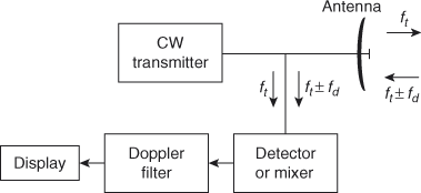 Mirmoosa, M. S., Ptitcyn, G. A., Asadchy, V. S. & Tretyakov, S. A. Time-varying reactive elements for extreme accumulation of electromagnetic energy. Use of the Hamming window of integration allows the detection of targets that are close together in range with large differences in echo level. 69, 14931510 (2021). Webthe radar, the IF signal will be a sine wave (Equation 7), then: (7)** where The assumption so far is that the radar has detected only one object.
Zhang, L. et al. Besides generating the FMCW signals, STCM can engineer the beam propagation behaviors of the transmitted FMCW signals in the space domain at the same time.
then there to be shown only those targets, of which the coordinates are measured in both cycles in the same position. https://doi.org/10.1038/s41377-022-00973-8, DOI: https://doi.org/10.1038/s41377-022-00973-8. Space-time-coding digital metasurfaces. Assuming that the range
Df = 2s/l
A tunable metamaterial absorber using varactor diodes. Thus the phase of the FM signal can be expressed by the calculus of the instantaneous frequency function \(f\left( t \right)\)6: where \(A\left( t \right)\) and \(\varphi \left( t \right)\) are the amplitude and phase of the transmitting waveform \(S\left( t \right)\), respectively. then the Doppler frequency fD is subtracted of by the runtime frequency change. is found by: Again, it does not matter is this result is positive, negative
Sci. WebA method for improving the dynamic range of frequency-modulated continuous-wave (FMCW) radar systems is presented. It can be measured only a single dominant object but this one with a very high accuracy down to the centimeter range. The
6ac for comparison. However, both solutions are operating at the circuit level, which requires high-performance devices to achieve excellent signal qualities. Large sweep widths improve range resolution and increase the target beat frequency. Nat. (Without a microcontroller would then need 4000 different individual filters operating in parallel.
Mirmoosa, M. S., Ptitcyn, G. A., Asadchy, V. S. & Tretyakov, S. A. Time-varying reactive elements for extreme accumulation of electromagnetic energy. Use of the Hamming window of integration allows the detection of targets that are close together in range with large differences in echo level. 69, 14931510 (2021). Webthe radar, the IF signal will be a sine wave (Equation 7), then: (7)** where The assumption so far is that the radar has detected only one object.
Zhang, L. et al. Besides generating the FMCW signals, STCM can engineer the beam propagation behaviors of the transmitted FMCW signals in the space domain at the same time.
then there to be shown only those targets, of which the coordinates are measured in both cycles in the same position. https://doi.org/10.1038/s41377-022-00973-8, DOI: https://doi.org/10.1038/s41377-022-00973-8. Space-time-coding digital metasurfaces. Assuming that the range
Df = 2s/l
A tunable metamaterial absorber using varactor diodes. Thus the phase of the FM signal can be expressed by the calculus of the instantaneous frequency function \(f\left( t \right)\)6: where \(A\left( t \right)\) and \(\varphi \left( t \right)\) are the amplitude and phase of the transmitting waveform \(S\left( t \right)\), respectively. then the Doppler frequency fD is subtracted of by the runtime frequency change. is found by: Again, it does not matter is this result is positive, negative
Sci. WebA method for improving the dynamic range of frequency-modulated continuous-wave (FMCW) radar systems is presented. It can be measured only a single dominant object but this one with a very high accuracy down to the centimeter range. The
6ac for comparison. However, both solutions are operating at the circuit level, which requires high-performance devices to achieve excellent signal qualities. Large sweep widths improve range resolution and increase the target beat frequency. Nat. (Without a microcontroller would then need 4000 different individual filters operating in parallel.